Core Loss
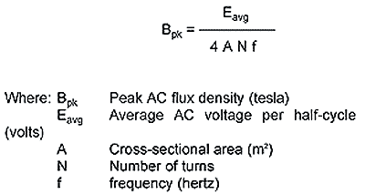
| Core losses are a result of an alternating magnetic field in a core material. The loss generated for a given material is a function of operating frequency and total flux swing (ΔB). The core losses are due to hysteresis, eddy current and residual losses in the core material. Core loss curves for each material are shown on each material page. This information results from sinewave core loss measurement made on a Clarke-Hesse V-A-W Meter. These curves have a typical tolerance of ±15%. The core loss in milliwatts per cubic centimeter (mW/cm3) as a function of peak AC flux density in gauss is shown for various frequencies. View Core Loss Comparison Table. This table provides a quick comparison of core loss in mW/cm3 at various frequencies for a given AC flux density for each material. The relative core loss comparison between materials at other AC flux densities will differ according to each materials response to operating AC flux density. The formula to calculate the peak AC flux density for an alternating signal based on the average voltage per half-cycle in SI units is:
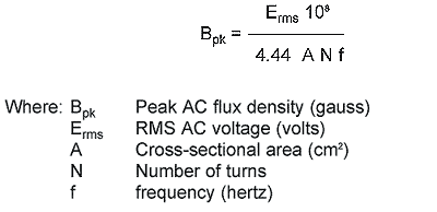
in cgs units, the following formula is commonly used for a sinewave signal with voltage in rms:
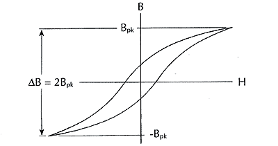
The factor of 108 is due to the Bpk conversion from tesla to gauss (1 tesla = 104 gauss) and the cross-sectional area (A) conversion from m2 to cm2 (m2 = 104 cm2). The change in constant from 4 to 4.44 is due to the form factor of a sinewave. Since the form factor is equal to the rms value divided by the average value for a half-cycle, the form factor for a sinewave is 1.11 (π/(2√2). The form factor for a square wave is 1.00. This formula is useful in determining the peak AC flux density (Bpk) to be used with the core loss curves for sinewave applications such as 60 Hz differential-mode line filter inductors, resonant inductors in power supplies, and for the fundamental line frequency signal in power factor correction chokes. Under this condition, the core experiences a total peak to peak AC flux density swing (ΔB) that is twice the value of peak AC flux density (Bpk) calculated with the above formulas as illustrated:
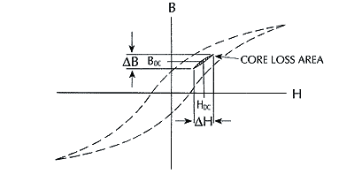
In inductor applications where the total losses are dominated by core loss rather than copper loss, an overall improvement in performance can be achieved by using a lower permeability core material. This is typically the case in high frequency resonant inductors. By utilizing a lower permeability core material (such as -2 Material μ = 10), additional turns will be needed to achieve the required inductance. While additional turns will increase the winding losses, it will reduce the operating AC flux density which will result in lower core loss. It is possible to introduce a discreet air gap into ferrite structures to lower their effective permeability and, thus lower the operating flux density. However, a discreet air gap can cause severe localized gap loss problems. This is particularly true at frequencies above 100 kHz. In many cases the gap loss will exceed the core loss. Since iron powder cores have a distributed air gap, these localized gap losses are essentially eliminated. To illustrate the core loss benefit of a lower permeability material, consider that an inductor of a given value on -2 Material (μo = 10) will require about 87% more turns than an inductor on -8 Material (μo = 35). The greater number of turns on the -2 Material will result in an AC flux density which is about 53% of the -8 Material flux density. Consequently, the inductor on the -2 Material will exhibit about 1/4 the core loss of the inductor on the -8 Material. In general, the -2 and -14 Material is recommended for resonant inductor applications. One of the most common applications for iron powder cores in switching power supplies is DC output chokes. In this application, the coil is biased with DC current along with a smaller percentage of ripple current which results from a squarewave voltage. The DC current generates a DC flux density and the squarewave voltage produces an alternating (AC) flux density. Biasing a magnetic material with DC current will shift the minor alternating BH loop but will not have a noticeable effect on the core loss. It is only the alternating flux density (ΔB) that generates core loss. This condition is illustrated:
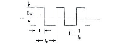
Core loss measurements made at the same frequency and total flux density swing (ΔB) produce only slightly higher core loss for squarewaves than for sinewaves. The following diagram describes a typical squarewave voltage across an inductor in a switching power supply:
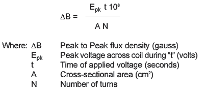
Since the volt-seconds (Et) during the "on" and "off" portion of a period must be equal in the steady state, the peak to peak flux density for a squarewave (which is not necessarily symmetric) is described by the following formula in cgs units:
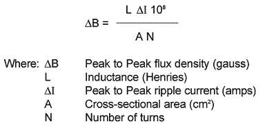
Another representation of this formula which can also be useful for these applications in cgs units is:
In unipolar applications such as flybacks, the preceding formulas which describe the total peak to peak flux density need to be used to verify operation within the maximum flux density limit of the core material to avoid magnetic saturation.
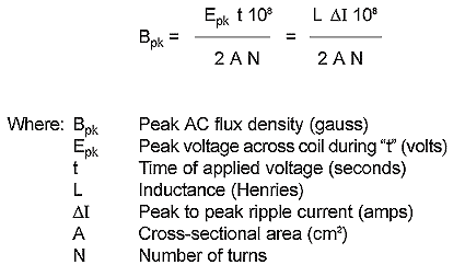
The following formulas should be used to calculate the value of peak AC flux density to be used with the core loss graphs of specific materials to determine the high frequency core loss in iron powder cores for a variety of DC biased inductor applications:
Inductors in active power factor correction boost topologies do not have the simple steady state waveform presented before. Rather, the high frequency signal (typically 100 kHz) is such that both the peak voltage across the inductor (E) and the "on" time (t) are constantly changing throughout the period of the fundamental line frequency (50 or 60 Hz). The core loss in this case will be the time-averaged core loss of the individual pulses for the period of the line frequency. Please refer to Power Factor Boost Preregulator Core Loss Calculations for information on the interpretation of core loss in active PFC inductors. |
353 West Grove Avenue, Orange, CA 92865, U.S.A.
1-800-679-3184
e-mail: sales@coilws.com
© 1996 - 2011CWS ByteMark & ByteMark
All Rights Reserved
