TRANSMISSION LINE TRANSFORMERS
|
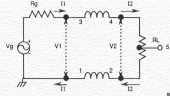
Theory The earliest presentation on transmission line transformers was by Guanella in 1944 1. He proposed the concept of coiling transmission lines to form a choke that would suppress the undesired mode in balanced-to-unbalanced matching applications. His 1:1 balun, also known as the Basic Building Block, is shown in Figure 1. The choking reactance, which isolates the input form the output, is usually obtained by coiling the transmission line around a ferrite core or by threading the line through ferrite beads. The objectives, in practically all cases, are to have the characteristic impedance, Z0, of the transmission line equal to the value of the load RL, (which is called the optimum characteristic impedance) and to have the choking reactance much greater than RL (and hence Z0). Meeting these objectives results in a 'flat' line and hence maximum high-frequency response and maximum efficiency since conventional transformer currents are suppressed.
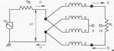
By combining coiled transmission lines in parallel-series arrangements, Guanella was able to demonstrate very broadband baluns, with ratios of 1:n2 where n is the number of transmission lines. Figure 2 shows the schematic for his 1:4 balun. His simple and important statements, "a frequency independent transformation," which appeared in his paper, had been overlooked by almost everyone as is evidenced by the scarcity of information in the literature on his approach to this class of transformers. Using straight, beaded lines or having sufficient separation between bifilar windings on a core, results in near-ideal transformers. Further, Guanella's baluns can also be easily converted to very broadband ununs (unbalanced-to-unbalanced transformers) by accounting for their low-frequency circuit models.
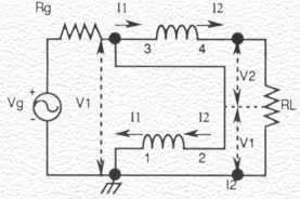
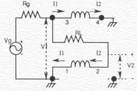
Ruthroff presented, in his classical 1959 paper 2, another technique for obtaining a 1:4 impedance transformation. It involved summing a direct voltage with a delayed voltage which traversed a single transmission line. Figure 3(A) shows his 1:4 unun and Figure 3(B) his 1:4 balun. Figure 3(A) shows the basic building block connected in the 'boot-strap' configuration. By connecting terminal 3 to terminal 2, the transmission line is 'lifted up by its own bot-Tstraps' to V1. The choking reactance of the winding prevents conventional transformer currents to flow resulting in a voltage of V1 + V2 across load RL. Figure 3(B) shows the basic building block connected in the 'phase-inverter' configuration. Since a negative potential gradient now exists along the transmission line, the voltage across the load RL is now V1 on the left side and -V2 on the right side.
Since Ruthroff's transformers summed a delayed voltage with a direct voltage, his transformers had a built-in, high-frequency cut-off. Although his transformers don't have the inherent high-frequency response of Guanella's transformers (which sums voltages of equal delays), they are easier to construct and many of his ununs should find use in matching 50 ohms to 12.5 ohms in the 1.5MHz to 30MHz range. This also includes rod transformers which do not possess as high a choking reactance because of the much higher reluctance of the large air-path for the magnetic field. Further, Ruthroff's 'boot-strap' technique has been the basis for the author's very broadband fractional-ratio ununs which use higher-order winding (trifilar, quadrifilar, etc.). 1 - Guanella G. 'Novel Matching Systems for High Fequencies,' Brown-Boverie Review, Vol 31, September 1944, Pages 327-329 2 - Ruthroff CL, 'Some Broad-Band Transformers', Proc IRE, Vol 47, August 1959, pages 1337-1342 |

353 West Grove Avenue, Orange, CA 92865, U.S.A.
800-679-3184
© 1996 - 2002 CWS ByteMark
All Rights Reserved