Comparison Between Nanocrystalline and Common mode choke for RFI Filters
|
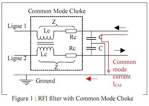
In most of the places of industrial and domestic power supplies, we meet nowadays some Switch Mode Power Supplies (SMPS) allowing tailored and volume reduced energy providers. As a consequence the occurrence of mutual electromagnetic interference between components strongly increase, leading to possible failures of electronic devices used in the neighborhood of each other such as computer, electronics for measurements and electrical machines. As well to control RF emission as to resist to interference, some standards such as EN 55011 provide standard values: peculiarly some frequency dependent limits of noise voltages To control and calibrate conducted noise (<30MHz), the Radio Frequency Interference (RFI) Filters are used; these filters are based mainly on Common Mode Chokes (CMC) surrounded by capacitors and inductances. The noise spectrum from SMPS is generally concentrated from 20kHz to 200kHz, with discrete harmonic components, whereas the noise spectrum from inverters is spread from 10kHz to 30MHz and has to stay under limits depending on applications. The goal of CMC is to reduce the noise voltages below these limits, inside this frequency range. | |||||||||||||||||||||||||||||||||||||||||||||||||||||||||||||||||||||||||||||||||
|
|
| ||||||||||||||||||||||||||||||||||||||||||||||||||||||||||||||||||||||||||||||||
|
It comes thus:
| |||||||||||||||||||||||||||||||||||||||||||||||||||||||||||||||||||||||||||||||||
|
with N the total number of turns of
the CMC, S the iron cross section of
the core, L the mean iron path
length and µdyn the dynamic
permeability of the core which
depends strongly (see after) on the
noise frequency f and the noise field
strength N.ICM/L .
To keep the maximum damping
effect of Lc in working conditions,
the design of the core has to prevent
from magnetic saturation, which is
to say B(f, N.I, N.ICM/L) < saturation.
It leads to the condition |
|
||||||||||||||||||||||||||||||||||||||||||||||||||||||||||||||||||||||||||||||||
|
µdyn< Js.L / (N.ICM ) = Max(µdyn)
(2) |
|||||||||||||||||||||||||||||||||||||||||||||||||||||||||||||||||||||||||||||||||
|
It comes out the rules for designing Common Mode Choke:
The design optimization process will be explained in detail in the full paper. Requirements for magnetic cores in Common Mode Chokes are the following ones:
| |||||||||||||||||||||||||||||||||||||||||||||||||||||||||||||||||||||||||||||||||
Table 1: main characteristics of magnetic materials for Common Mode Choke | |||||||||||||||||||||||||||||||||||||||||||||||||||||||||||||||||||||||||||||||||
|
Recently the mergence of nanocrystalline materials in Power electronics
applications move the choice of component designers toward more compact
structure when comparison is made with previous magnetic materials for CMC such
as Co-based or Fe-based amorphous, MnZn ferrite and 80%Ni permalloys. The main
requirements for CMC are very well fulfilled with nanocrystalline materials in
terms of high dynamic permeability, high saturation, high thermal stability (see
table), providing strong ability to reduce substantially the CMC volume. This paper aims to detail the design of CMC, to compare actual competing solutions (ferrite and nanocrystalline) in terms of dynamic permeability, insertion attenuation and final component volume as a function of the technological choice made by designers (N, S,L). The main results are briefly presented hereinafter: Insertion loss and the main designing features: The insertion loss – also called insertion attenuation – represent the damping ability of the CMC, defined as Ins.Loss= 20log(V1/V2) where V1 is the voltage when the CMC was not inserted between the signal generator and the level meter, and V2 is the voltage when it was inserted between the signal generator and the level meter. The voltage ratio V1/V2 is directly connected to the impedance Z of the CMC, and then in the lower frequency range (0.01 – 1MHz) the insertion loss will be determined by the inductance of the CMC, whereas in the higher frequency range (1 – 100MHz) the insertion loss is mainly dependent on winding capacity. As a consequence at low frequencies, L and the damping effect are improved (see eq. 1) by an increase of the number N of turns (see figure 3 for nanocrystalline with a constant µr = 20 000) or by an increase of permeability (see figure 4 for ferrite and Nanocrystalline with N=50 turns) | |||||||||||||||||||||||||||||||||||||||||||||||||||||||||||||||||||||||||||||||||
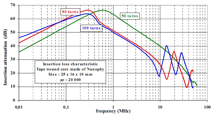 Figure 3: Insertion loss versus frequency in the case of a Common Mode Choke for RFI filter, with a magnetic nanocrystalline wound core made of Nanocrystalline - µr = 20 000 – and three possible numbers of turns | |||||||||||||||||||||||||||||||||||||||||||||||||||||||||||||||||||||||||||||||||
| It can be observed from Figure 4 when ferrite N30 and nanocrystalline - µr=20 000 are compared, that in spite of the higher permeability of the latter (dynamic permeability magnitude is going on the contrary than cut off frequency) this one (nanocrystalline) exhibits the advantage of a damping effect acting in a wider frequency band: this advantage is taken from large eddy currents effects in nanocrystalline materials and can be observed when capacitive effects remains at a rather low magnitude (case of low number N of turns) as in Figure 4. When N increases (figure 5), capacitive effects become rapidly predominant near resonance and then the exactly same insertion attenuation behavior is obtained for high frequencies. | |||||||||||||||||||||||||||||||||||||||||||||||||||||||||||||||||||||||||||||||||
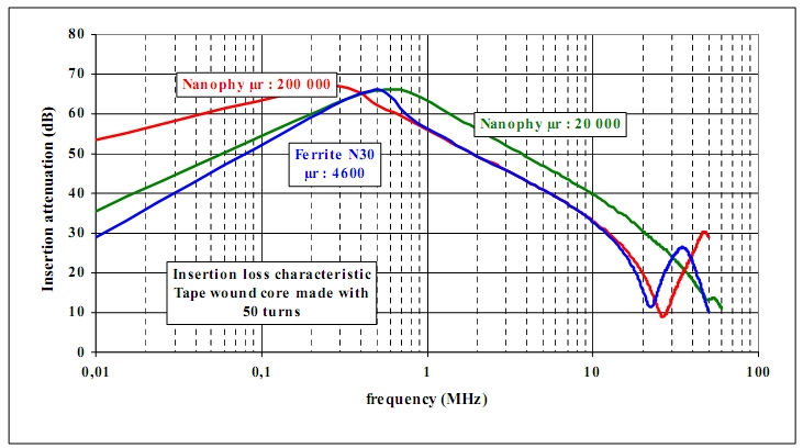 Figure 4: Insertion loss versus frequency in the case of a Common Mode Choke with 50 turns for RFI filter, with a magnetic core made of nanocrystalline wound - µr = 20 000 or µr = 200 000 – or N30 ferrite -µr = 4600. | |||||||||||||||||||||||||||||||||||||||||||||||||||||||||||||||||||||||||||||||||
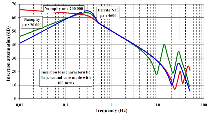 Figure 5: Insertion loss versus frequency in the case of a Common Mode Choke with 100 turns for RFI filter, with a magnetic core made of nanocrystalline wound - µr = 20 000 or µr = 200 000 – or N30 ferrite -µr = 4600. | |||||||||||||||||||||||||||||||||||||||||||||||||||||||||||||||||||||||||||||||||
|
These comparisons between CMC-solutions have been made to point out the
different frequency behaviors of insertion loss, depending on nature of magnetic
materials, permeability and number of turns; but till to now no requirement
about non-saturation and volume reduction has been taken into account in such a
description process. It’s the goal of the second part: to compare the ability of
each material to reduce the core volume, taken into account the whole
requirement of CMC Compare the ability for each magnetic material to reduce the volume of the core: use of a designing tool: A simple software is used as a tool to design industrial CMC starting from ferrite material and from nanocrystalline material; the design process describe the needs of non saturation under the low frequency load, of standing above minimum impedances at specified frequencies (typically 10 and 150kHz), reducing the volume of the core. A multi-variable computation is made to get the best technological and economical compromises between core volume and dimensions, number of turns, wire diameter, number of wire layer… From calculations, it comes out a proper comparison between ferrite and nanocrystalline as shown in table 2 in some industrial cases where the volume of the component is imposed and the volume of the core has to be minimized. It clearly points out that the volume of the core can be reduced by 50 to 80% when an appropriated ferrite is replaced by a well-chosen nanocrystalline core, as a result of its superimposed advantages of high and tailored permeabilities, high saturation and inductive behavior near CMC resonance. | |||||||||||||||||||||||||||||||||||||||||||||||||||||||||||||||||||||||||||||||||
Table 2: Comparison between nanocrystalline and ferrite dedicated to final core volume after designing from imposed component volume | |||||||||||||||||||||||||||||||||||||||||||||||||||||||||||||||||||||||||||||||||
 (1)
(1)
353 West Grove Avenue, Orange, CA 92865, U.S.A.
1-800-679-3184
e-mail: sales@coilws.com
© 1996 - 2011CWS ByteMark & ByteMark
All Rights Reserved